Combines/Harvesters
Designing a controlled traffic system
November 30, 1999 By Bruce Barker
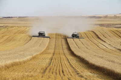 Steve Larocque built his CTF system around 30-foot headers and a 10-foot wheel stance on his combines. Editor’s note: This is another installment of the Top Crop Manager series on Controlled Traffic Farming.
Editor’s note: This is another installment of the Top Crop Manager series on Controlled Traffic Farming.
Getting started in controlled traffic farming (CTF) systems can be daunting at the beginning. The difficulty is getting all machinery tires to follow the same permanent tramlines. Steve Larocque and his brother-in-law Mitch Currie moved to controlled traffic on their 640-acre farm at Morrin, Alberta, in 2010, and with a year of experience under their belts, offer some guidance on designing a CTF system. The good news is that it does not have to cost a lot, and growers can move into CTF in stages. “It all starts with the combine header. The limitation is that you have to be able to spread the straw and chaff the full width of the header; otherwise, the residue will build up in the centre of the header width and cause fertility issues or seed placement issues,” explains Larocque, who also runs his own crop consulting business, Beyond Agronomy. Currie’s father Sam was also an integral part of the modifications, leading the way with mechanical adjustments.
Another reason to start with the combine is that typically it carries the most weight in the field, and is the most costly to modify. Most combines have wheel track widths on 10-foot centres, so setting up a CTF system means the other implements must run on 10-foot centres as well. The combine header, though, must be a centre delivery, and cannot be offset.
A common way to set up a smaller CTF system is to use a 3:1 ratio for machinery widths. In Larocque’s case, having a 30-foot-wide combine header, meant using a 30-foot-wide air drill and a 90-foot-wide sprayer boom.
In Australia, some larger farms have gone with a 2:1 ratio, using a 30-foot combine header, 60-foot air drill and 120-foot sprayer boom. Using these types of ratios ensures the combine, tractor and sprayer tires all follow the same tramlines.
Making axle modifications
With Larocque’s combine wheel width on 10-foot centres, he had to modify his 4WD Steiger tractor’s stance. The tractor had dual wheels on 11-foot, six-inch centres. They took off the inside duals, cut 7.5 inches off of each spacer, put them back in for stability, then welded both rims together. The rims were then sandblasted and painted. The stance ended up on 10-foot, three-inch spacing. “If we were to get down to a precise 10-foot width, we would have had to cut the rims and compromise the integrity of the structure and we didn’t want to go that far,” says Larocque.
The tire load capacity on the tractor was a concern, but fell just within load limits. The tires are 23.1–34 bias ply tires with a load rating of 7500 pounds at 20 psi. The four of them can carry 30,000 pounds, which is about the tractor weight. The cost of the tractor tire modifications was approximately $1800.
Fortunately, the Brandt SB 4000 suspended-boom sprayer stance was naturally on 10-foot centres, so the only modification to the sprayer was to cut 10 feet off the 100-foot boom to bring it down to 90 feet wide.
Downsizing the air drill
Their drill was a 40-foot, five-section Concorde. To bring it down to 30 feet, they simply had to remove a section from each end. Challenges arose, though, in getting the hydraulics to work properly and the air distribution system set up.
After taking the two wing sections off, the hydraulics developed an air lock, and the wings would not go down completely.
The manufacturer actually told Larocque that they could not successfully cut down the drill to 30 feet because of the different ram sizes in the hydraulics. After two days, they were finally able to eliminate the air lock and get the drill levelled.
The drill was originally set up as a single-shoot system, so they bought different distributors to allow double-shoot seeding.
In setting up the system, they decided to leave the tramline unseeded, but double up the seeding rate on the seed row on each side of the tire track. However, these doubled seed rows had only one fertilizer tube. Seeding on 12-inch centres meant four fertilizer distributors with seven tubes each, and four seed distributors with eight seed tubes each. “The theory was that the seed row adjacent to each track would have more sunlight and moisture, which could result in later maturity. Doubling up the seeding rate on each side with two seed rows helped avoid that problem,” explains Larocque.
The 230-bushel air cart did not have matching axles, so axle extensions were added on to the back wheels to bring them to 10-foot centres. When they hit the field, the air cart was not following the tractor tracks. Larocque found the alignment on the air cart was off by one-eighth of an inch, and resulted in the wheel alignment drifting off by one foot. They tweaked the tie rods to pull the air cart back into alignment. “How many people check the alignment on their air cart?” asks Larocque.
Only the four air drill castor wheels run outside the tramlines, but Larocque believes there is not a lot of weight on the wheels with a 30-foot drill, so he can live with that.
Get out the measuring tape
Assuming the combine header was 30 feet wide, Larocque took a measuring tape to it one day and found the cutter bar width to be only 29 feet, eight inches. Thinking that would be a problem, he measured the air drill and found it to be only 29 feet wide from shank to shank, which actually turned out to be a positive. Seeding on 12-inch centres and inter-row seeding meant that moving the offset hitch six inches each year left two inches of room on one side of the header and three inches on the other. His set-up actually under-laps each pass with nine inches one way and 15 inches the other way. The increased efficiency has improved operating time and virtually eliminated seed and fertilizer overlap.
Setting up for inter-row seeding meant modifications to the hitch. Normally, seeding between the rows with RTK guidance meant driving six inches to the side of last year’s stubble on 12-inch centres. However, because CTF means staying on the same tramline from year to year, Larocque had to modify his hitches to keep the tractor and air cart tires on the tramlines.
Originally, they built a hitch with a three-inch offset on the left and were planning on flipping it over to provide a six-inch offset to seed between the rows. Instead, they will keep the three-inch offset to the left on the hitch, but now will flip it over on to the right side to come back six inches to the right. “This will give us our inter-row seeding and avoid any unharvested strips this fall. We had three inches of room on one side of the header this year and two inches on the left, meaning 29.3 feet of the header was full of crop out of 29.8 feet. With the modifications, we’ll be three inches off-centre one year to the left, and then three inches off-centre to the right on the following year, to give us our six-inch, side-to-side move each year to match our 12-inch row spacing. We will have to make the same modification to the offset hitch on the air tank as well,” explains Larocque. “If we didn’t make this hitch modification, we would have left a two-inch unharvested strip every other year.”
The most expensive part of the conversion was the move to RTK autosteer. The total cost was $16,000, but the system is necessary to allow Larocque to go back to the same tramlines year after year. “The biggest question I still struggle with, and I don’t have an answer for it, is logistics at harvest. We run up and down the field, and don’t have a grain cart, so we unload on the headlands,” says Larocque.
This approach means the combine is sometimes unloaded when it is not full, or the combine might fill up halfway down the field. A grain cart with an extension on the combine auger is one solution to allow unloading on the go in the field, but is an added expense.
Overall, Larocque is happy with how the system performed in 2010, but still wants to look at how to manage residue behind his Gleaner to get more uniform spread of straw and chaff.
| Controlled Traffic Farming Alberta project moving ahead Controlled Traffic Farming Alberta (CTFA) was formed as a farmer-led initiative aimed at evaluating CTF in Alberta in 2010. The Alberta Crop Industry Development Fund, Alberta Canola Producers Commission, Alberta Barley Commission, Alberta Pulse Growers and Alberta Winter Wheat Producers Commission provided one year of funding. The Agricultural Research and Extension Council of Alberta was the managing partner. CTFA is moving ahead with a three-year project to evaluate and assess CTF systems in Alberta and to reduce the risk of adoption. Peter Gamache is the project leader on CTFA and says the group hopes to have six to nine CTF demonstration sites across Alberta to help farmers gain a better understanding of the potential benefits and risks in moving to CTF. “The project is designed to be farmer-driven. The assessment of CTF will be field-scale, on-farm using farm-scale equipment and farmers/industry expertise at the same sites over three to five years,” explains Gamache. |